W.I.P. Grand Prix de Trois-Rivières road layout

Discussion in 'Tracks' started by NiTZHD, Jun 5, 2020.

  1. NiTZHD

    NiTZHD New Member

    Joined:
    Jun 2, 2020
    Messages:
    7
    Likes Received:
    12
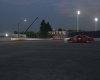
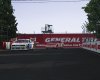
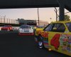
    Hi guys, I recently realized that one of the only Canadian track we were not able to race in assetto corsa was my hometown track. So I decided to try to bring the GP3R road layout to Assetto Corsa.

    Years ago we had the very well done Gilles Benoit rfactor mod. So I decided to contact him to get the authorization to convert the track to AC. With the authorization granted i've contacted DSirois a friend of mine who already did some work on the RX GP3R track for AC and Maruto who worked on the Vallée du parc 2020 track (another place near my hometown) to get some help.

    So here his my plan:
    1- Convert the 2005 rfactor mod to Assetto Corsa and learn the basics of AC track modding
    2- Update the texture to more up to date ones
    3- Update track minor changes from 2005 to 2020
    4- Eventually get acces to LiDAR and/or survey to update track bumps.

    So feel free to comment and help if you can! An alpha release should be released soon.

    [​IMG]
     
    Last edited: Jun 5, 2020
    FFF789, maruto, Tibor Solyom and 2 others like this.
  2. Gunnar333

    Gunnar333 Well-Known Member

    Joined:
    Aug 5, 2017
    Messages:
    321
    Likes Received:
    618
    Location:
    Germany
    Hehe, I'm sure if you get LIDAR data for it you will end up in redoing the whole track. :lol:
     
    luchian likes this.
  3. Johnr777

    Johnr777 Moderator

    Joined:
    Jul 26, 2017
    Messages:
    1,048
    Likes Received:
    613
    I agree, the rF version will be far from accurate.

    But here is the lidar :)

    https://www.foretouverte.gouv.qc.ca/

    Annotation 2020-06-08 085912.png
     
    haunetal1990, FFF789, maruto and 2 others like this.
  4. Martin Dupuis

    Martin Dupuis New Member

    Joined:
    Aug 1, 2018
    Messages:
    24
    Likes Received:
    10
    Yes, that would be wonderful. If I had any 3D skills, I'd help you.
    I can test the track though, plus I know of a former marshal of many years there. Knows every corner and bump.
     
  5. NiTZHD

    NiTZHD New Member

    Joined:
    Jun 2, 2020
    Messages:
    7
    Likes Received:
    12
    Hey guys, just some more infos. The project is still WIP. From how the rFactor mod was made I cannot just do a convertion I will have to do a lot of modelling so just dont hold your breathe. Mean while I've done the rFactor2 conversion so we can practice in the down season with a Formula 1600 mod. If someone is interested just pm me.
     
    EKO Sim-Racing and Gunnar333 like this.
  6. maruto

    maruto Active Member

    Joined:
    Apr 28, 2020
    Messages:
    126
    Likes Received:
    218
    Hello NiTZHD, someone just made the Gilles Benoit RF1 conversion to AC:

    the download link is on his site: http://www.assetto-fr.tk/AC-Forum/

    I'm not sure he asked permission or even know it is a Gilles Benoit track, but it is now available to AC.

    The circuit is completely flat and is completely outdated, has no bumps or sponsors...

    But I think Gilles Benoit did an incredible job for 2005 and the track is really highly detailed , marshalls, tv cameramen, lots of scarfolders, buses, crane, lightpoles with lightning meshes, duplessis door... i think it has a lot of potential to be upgraded, keeping his excellent work on the and upgrading it to 2020 AC ....

    I agree with Gunnar333 and johnr777 it would be better to start this project from the beginning and redo everything from scratch using lidar data but since a lot has been done already, isn't there a way to pursue Gille's work and keep it alive?

    I would like to contibute on that. Trois Rivières is a track that is located 30min from where i grew up, when NiTZHD contacted me to work on that project i was really pleased to do so... but I would need help, i am still learning ....

    I have already spend the last two days working on a skin to upgrade the textures and add 2019 GP3R sponsors based on the last GP held there: I'm not 100% accurate, but the spirit is definitively there. with the correct config file it is already looking much better.

    that's the easy part.

    To me the main problem is the flat road. this is a street circuit, just looking at the videos you know it is really bumpy. I am thinking about the lidar data but i don't have the programs required to extract the data 3D model from the site Johnr777 is refering to. @Johnr777 could you help me on that point?

    there is also the height map method described by @fughettaboutit here :
    , but i think it might be good for mountains, but not precise enough for road bumps... (?)

    there is a third option wich i think i will go for because i already experimented on it twice ( Vallee du parc and baskerville update) and i want to improve that method ... it is similar to lilsky's method of adding noise. It is to recreate a point cloud from a mesh/surface, add camber, principals road declivity and thenstart mess around with a script to recreate microbumps... (i described it here) I haven't found the perfect density but i'm pretty sur i will one day ;) It won't be accurate but at least it won't be flat. @Martin Dupuis can you tell me some more about thoses bumps, could you have your marshall buddy draw them roughly on a map of the circuit with the approximative height difference (in cm) could be a start...

    what do you think?

    any help is welcome, thanks, :whistle:


    Screenshot_legion_nascar_circa_1990_gp3r_11-7-120-17-42-44.jpg
     
    Last edited: Aug 14, 2020
    luchian likes this.
  7. Johnr777

    Johnr777 Moderator

    Joined:
    Jul 26, 2017
    Messages:
    1,048
    Likes Received:
    613
    If you do have permission to use Gile's track side objects, then IMO, create the track from scratch and insert the objects after. There's no way to modify the existing track itself to LiDAR.

    Regarding bumps, that should be after you finalize the visual meshes. And forget about using the aerial data for that. It will need to be done based on onboards or any other reference you can find.

    I'll get the lidar for you, but first want to make sure I'm not wasting my time, need hear that you are ditching this conversion :)
     
    luchian and maruto like this.
  8. maruto

    maruto Active Member

    Joined:
    Apr 28, 2020
    Messages:
    126
    Likes Received:
    218
    ditching means to give up? well don't know about that, some things takes times, sometimes you thinks it is abandonned, but it is not!!

    Like i said, it make sense to me to give that track some love, it deserve it: I like the layout, it is the "big city" of la Mauricie, 30kms from my hometown. grew up there, have very bad memories about Trois-Rivières, but some goods too, my friends studied there, i know the city very well.

    I beleive Nitzhd got the permission to work on the conversion, I will ask him to give me Gilles 's contact so i can ask him myself. Or i'll find a way to contact him.

    with his permission about the assets, i could start working it from scratch, like i did with my first track (wich is not finished, yet not abandonned) not scared of that. But i'm still learning, It just takes time and it won't be a two days (week, month) project. That track has lots of small texture, no atlas, not really optimized for AC. I know i won't have the time to redo all assets, all buildings, all trees all everything, this is not possible for me right now. that's why i was opting for an additive non destructive update and work only on the physical mesh.

    feel free to help me with lidar data, i would prefer that you explain to me how to do it and what tool i need so i can use the knowledge for future project... I've asked you that question about the lidar data from that site in june, (mont tremblant thread, yet another Québec track) I'm still really interested:)

    but i you can get it for me i'll be in your debt. don't want to waste anybody's time, just want to learn and create stuff that didn't exist before. but then i'll ask questions to you.


    (btw you commented about track optimization on my baskerville update, i think i have a way to do it to reduce the polycount of tyres, need to redo that also. and bring Vdp to 0.6, i get distracted )

    have a good day mr John.
     
  9. Johnr777

    Johnr777 Moderator

    Joined:
    Jul 26, 2017
    Messages:
    1,048
    Likes Received:
    613
    For Mt Tremblant I was only able to grab data in TIF format, which required Global Mapper, then convert to LAS to bring it into Cloud Compare, then to a 3D format for blender of 3DS Max.

    I'll look again at the Trois Rivieres area.

    When I said "ditching" the conversion, I was mainly talking about the road mesh. Anything coming from the rF1 days is really dated, lower detail, etc.

    But you wont be able to update the existing track with lidar, I guarantee some corners will be way off.
     
  10. maruto

    maruto Active Member

    Joined:
    Apr 28, 2020
    Messages:
    126
    Likes Received:
    218
    thanks for the info, so Global mapper is really needed? I was able to get those TIF files but could'nt find a way to open them. Is Global mapper the only program used to process that data? the price seemed a little high to me...not sure i can afford it just to convert data from one program to another.

    After processing the TIF files, what comes out? LAS you say? that goes into cloud compare? I watched Lislsky video about it but didn't understood with no example on hand....(I need practical example.), and then you can export point clouds using what format? i use Rhino, can import almost anything execpt.max files :)

    ...
    I'm curious to compare..

    i am looking at the mesh definition right now from Gilles, it has some amplitude in the Z axis so it is not completely flat, 5.7m around the Porte duplessis, 40 to 60 centimeter in average , but looking from above the point definition is really loose, one point every 2 meters in the corners, one every 10-25m or so in the straight...only one subdivision in width..

    upload_2020-8-12_18-55-18.png

    upload_2020-8-12_18-58-40.png

    My plan is to do so:
    -keep the external point of the original mesh
    -Offset the limits 10 cm to the inside and raise them +2.5cm in z axis, creating a bevel not too big when the car goes offroad, but still significative to feel it.
    -create a middle line and rise it 13cm to create a camber
    -create a new surface between those line
    -subdivide to have a high density mesh ( have to figure those numbers, Nordschleife definition is really dense, will try to go around that) so let's say aroud one point every 0.5m or so.
    -extract all intersection points on that surface
    -randomly move them to create microbumps
    -recreate a definitive physical mesh using those points and the one from the original limit
    -same thing for the visual mesh but with less definition.
    -replace the original mesh with those two.

    the cross section schematic looks like that:
    blue line actual mesh,
    black line visual mesh with camber,
    red line physical mesh with microbumps.

    upload_2020-8-12_19-25-5.png

    this shouldn't be too long, the testing is long to get something smooth yet not so smooth. Bumpy smooth.
    crunchy smooth...
     
  11. Johnr777

    Johnr777 Moderator

    Joined:
    Jul 26, 2017
    Messages:
    1,048
    Likes Received:
    613
    Im really confused... What's the lidar for then? seems you are set on working with the existing road mesh
     
  12. NiTZHD

    NiTZHD New Member

    Joined:
    Jun 2, 2020
    Messages:
    7
    Likes Received:
    12
    Wow guys you are awesome. I just sent an email to maruto with the info's I have and what I can provide. 360 videos, pictures, feeling of the track, field survey (GNSS), etc. Like I said right now I cannot but much effort into modelling but will do what I can to help.
     
    maruto likes this.
  13. maruto

    maruto Active Member

    Joined:
    Apr 28, 2020
    Messages:
    126
    Likes Received:
    218
    @Johnr777 sorry if my english is bad, not my native language... what i described above is just the method i imagined to create microbumps.

    Lidar data will tell me the exact borders of the track, once i get those borders as splines in good place and altimetry, i run the script to generate the hi res meshe.

    edit: , i just figured out what you meant by ditching the road mesh..... yeah, if i can get my hand on lidar data i'll ditch the road mesh and the grounds around and redo them to fit lidar . but i'll keep Gilles assets, just got his personal mail from nitzhd, and a copy of his approval to work on it.
     
    Last edited: Aug 14, 2020
  14. Martin Dupuis

    Martin Dupuis New Member

    Joined:
    Aug 1, 2018
    Messages:
    24
    Likes Received:
    10
    I can try to contact him and see what I can get.

    You can get video from all the events that were held there in the last few years on their official Youtube channel: GP3R. Sorry for you folks, it's in french only, but I tihnk you'll be fine with it @maruto ;)
     
  15. maruto

    maruto Active Member

    Joined:
    Apr 28, 2020
    Messages:
    126
    Likes Received:
    218
    thanks, every piece of information can be useful. Nitzhd lives next to the track, he already provided me with good onboard video of HIS raceteam driver, and can make survey on site for bumps locations and photos

    yeah i've been watching those 2019 replays for the last couple of days, trying to get all those sponsors on the right place ;)

    then i came across 2017 replay of IMSA prototype and found out about the lites series i didn't know about :

    lat-galstad-trois-rivieres-0816-6433.jpg

    elan dp02, god i love these!!

    ...

    such a fun track, so many different categories.

    This track will be amazing guys. And then hopefully Martin Brousseau will practise so much he will win 2021,'s edition ;)

    thanks.
     
    Last edited: Aug 14, 2020
  16. maruto

    maruto Active Member

    Joined:
    Apr 28, 2020
    Messages:
    126
    Likes Received:
    218
    I contacted Gilles this morning and he replied right away, he's thrilled to have us working on his track and about lidar implementation. he's interested in taking whatever improvement we do then to RF2. I invited him to join in this thread to keep up with the updates, and give a hand if necessary.

    Here's some photo of the overall ambiance with the 2017 sponsors:

    Screenshot_acfsk_ligier_jsp3_gp3r_15-7-120-12-11-22.jpg Screenshot_acfsk_ligier_jsp3_gp3r_15-7-120-12-11-0.jpg Screenshot_acfsk_ligier_jsp3_gp3r_15-7-120-12-10-11.jpg Screenshot_acfsk_ligier_jsp3_gp3r_15-7-120-12-9-46.jpg Screenshot_acfsk_ligier_jsp3_gp3r_15-7-120-12-5-35.jpg Screenshot_acfsk_ligier_jsp3_gp3r_15-7-120-12-4-9.jpg Screenshot_acfsk_ligier_jsp3_gp3r_15-7-120-11-59-0.jpg
     
  17. physicsimulation

    physicsimulation New Member

    Joined:
    Aug 18, 2020
    Messages:
    21
    Likes Received:
    12
    Location:
    Trois-Rivières, Qc, Cdn
    Martin Dupuis talked about your forum.
    I don't know if I can help.
    Here is a video, an exercice to extract vibration from onboard video,
    I tried aiming to the helmet in the miror, aiming onto the "hood", and finaly to the horizon (just at the right of the miror).
    The last try is the one I published.
    This onboard video has a lot of "rolling shutter" that makes difficult to stabilize.
    The stabilisation process give a text data file with 4DOF (hor, vert, rot, zoom)
    In my opinion, a good onboard with helmet rear view (the head shakes with bumps) video
    OR
    a helmet view like this one,
    (play it at 0,5 speed, in parameters)
    In this last one, the software corrects lens deformation in supplement to 3DOF.
     
    maruto and Won like this.
  18. maruto

    maruto Active Member

    Joined:
    Apr 28, 2020
    Messages:
    126
    Likes Received:
    218
    Hello mister ! Welcome to this discussion, if i get it right, this is really interesting and could be useful.

    From what i understand the data file could give us good information about the track surface related to the head movement analysed in the video.

    These results sorted, we could locate precisely the most important bumps and holes in the track.

    I have some question, are the head movement related to speed, ex small bump with great speed will produce similar effect than a big bump taken at lesser speed? So can we say the highest peak in the data won’t necessarily be at the biggest bumps?

    Anyway, I this this is really interesting to create a map of the most significant bumps or cracks in the circuit and then investigate them in situ later...

    (If we make a new on-board video at constant speed and with some markers could it help having better data?)
     
  19. physicsimulation

    physicsimulation New Member

    Joined:
    Aug 18, 2020
    Messages:
    21
    Likes Received:
    12
    Location:
    Trois-Rivières, Qc, Cdn
    You can use an AHRS (as per drone positionning) that relate GPS (for position) and accelero-gyroscope (IMU) conjugated with OBDII data (for speed and RPM), that is dataaaaaa.

    Or, use available onboard video to extract track roughness from some vibrations.

    Track roughness shakes the tyre patch RLCy connected to wheel hub RLCy connected to the car frame RLCy connected to driver body RLCy connected to the helmet.
    NOTE: RLCy means "resistance, inductance, capacitance", the "y" to create an adverb 8)
    (more useless reading https://www.scielo.br/scielo.php?pid=S1678-58782011000300005&script=sci_arttext&tlng=pt)

    You can attach the cam to the car frame seen a) some horizon (as stabilizer aim) and b) the wheel hub (to get his vibration)
    OR,
    with the same cam position, a) aim some horizon and b) get vibration from the driver's helmet
    OR,
    put the cam onto the driver's helmet and stabilize some horizon to infere the cam vibration.

    Infering track roughness from helmet motion is not direct (see the 4 RCL links) but, if you want to simulate driver seat vibration and/or induced tyre slip/grip, you have more data then nothing.

    Concerning speed and bump, they are frequency related (see graph in the preceding useless reading) and, through 4 RCL links, subject to interpretation.
    Take the Nissan Micra race, these suspensions are too soft and too much unlink helmet-track.
    Take open wheel car and the helmet-track link is more pertinent.

    To visualize speed and bump relative importance, imagine you bike on a railroad track.
    Going slowly, you are not able to drink a glass of water without spilling all over the place, due to low frequency.
    Going faster, you think you are sitting on a sawzall (120 Hz) and near concussion (commotion cérébrale), due to the higher frequency. (body resonance about 40 Hz ?)
    Going near speed of light (ok not so fast 8D), you fly, as water skiing, over the high frequency bump but feel fast occurence of long bump (genre wave).

    That means that bump interval decrease as speed increase. Imagine that bumps are going at you at the car speed, with the same amplitude. The only difference is the response of all RCL links between the road surface and the helmet.

    I create a new post specific to this issue.
    https://assettocorsamods.net/threads/track-imperfection-from-video-stabilisation.2250/
     
    Last edited: Aug 19, 2020
    maruto and luchian like this.
  20. luchian

    luchian Administrator Staff Member

    Joined:
    Jun 3, 2014
    Messages:
    3,007
    Likes Received:
    1,491
    I am still trying to understand what you are saying here :lol:, but if it means what I think I understand, it's actually a very interesting idea. And maybe a good source of data, when lidar & co are missing.

    LE: so, in a nutshell, you would extract "vertical" data from video?
     
  1. This site uses cookies to help personalise content, tailor your experience and to keep you logged in if you register.
    By continuing to use this site, you are consenting to our use of cookies.
    Dismiss Notice