TUTORIAL LIDAR (Point cloud) to mesh tutorial
- Thread starter DanTDBV
- Start date
Woodee
Member
Using the UK LIDAR resource (http://environment.data.gov.uk/ds/survey#/download) I am able to use point cloud data (LAZ format) and import into Cloud Compare. Other data (specifically LIDAR that is 25cm/50cm DTM/DSM) comes in ASC format. Has anyone had any luck importing ASC format into cloud compare? All I get is a collection of dots in a line in 3d view.
Willy Wale
Member
I think it was the ASC files I used. I'm on my phone but feom memory the file is only Z height data. I had to manipulate the file to add the X and Y coordinates before loading to Cloud Compare.Using the UK LIDAR resource (http://environment.data.gov.uk/ds/survey#/download) I am able to use point cloud data (LAZ format) and import into Cloud Compare. Other data (specifically LIDAR that is 25cm/50cm DTM/DSM) comes in ASC format. Has anyone had any luck importing ASC format into cloud compare? All I get is a collection of dots in a line in 3d view.
WW
Aureliano Buendia
New Member
Thanks for the very useful write-up.
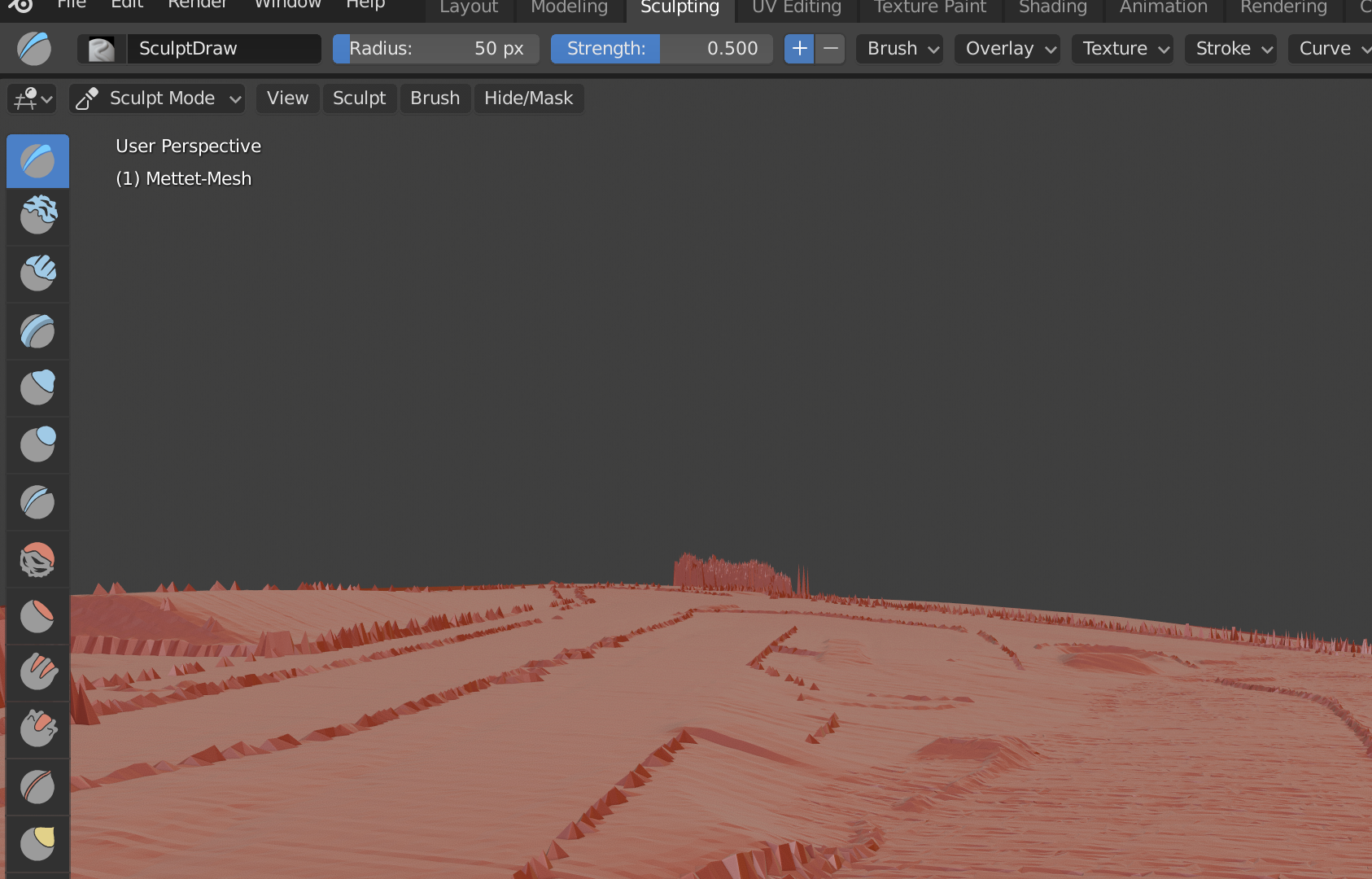
I've used a lidar point cloud to create this mesh. It's pretty much a cut-out from merged lidar data, directly made into a mesh in CloudCompare .
I'm noticing grooves in the mesh of (what i assume to be) units of lidar measurements. There's more visible on the right side, because there happens to be some overlap from two measurement flyovers.
Is that something you encountered as well? I'm worried if I smooth it out, I'm losing the details.
Sample size is 1 every 1,13m x and 1,14m y (==0.8/m^2). Is that comparable to what you used?
Would this need to fixed in Meshlab or Meshmixer, or does Blender work too?
I'm pretty much brand new to 3D modelling, so I hope I'm not asking anything stupid.
Pixelchaser
Well-Known Member
I doubt anybody would notice any changes you make on that right hand side. I think you could smooth that unless you re level it. and yes lidar at 0.8m is common. its exactly what to use. so this is your referencing layer, and you build layers for game world on it. but much less polygons of course. and the polygons for that would be just enough to capture the scenery. but there is no right or wrong, just good practices really and learning those mainly only comes from mistakes unless your following a write up or tutorial. and every track is different. iam sure there is further manipulation you can make in cloud compare, i am just not that familiar with it and as its only used a reference layer, it can have issues while the produced layers work fine
Last edited:
barf
Member
To remove the overlap you could interpolate the values and produce a geo-referenced DEM or DSM raster using blast2dem or rapidlasso. Then import your DEM/DSM using BlenderGIS or the built-in raster import thingy (assign value to Z axis). BlenderGIS can generate a TIN from the raster (WARNING: it's Delauney triangulation runs in a single thread).
The project I'm working on uses a LiDAR DEM as the visual and physical mesh in a 1400 square km scene, with orthophotos draped over that. This way the LiDAR is the actual mesh and a useful reference layer for object positions etc.
Edit: FWIW after all that there may still be grooves and undulations, if that's what the data contains")
The project I'm working on uses a LiDAR DEM as the visual and physical mesh in a 1400 square km scene, with orthophotos draped over that. This way the LiDAR is the actual mesh and a useful reference layer for object positions etc.
Edit: FWIW after all that there may still be grooves and undulations, if that's what the data contains
Last edited:
Aureliano Buendia
New Member
Mine is a bit smaller and easier than yours. I don't even have a full km² of data to cover the whole track.
I have the data of the surrounding landscape too, so I might still use that later on when I need to model global terrain features. It's mostly flat though. It may not even be useful.
I have the data of the surrounding landscape too, so I might still use that later on when I need to model global terrain features. It's mostly flat though. It may not even be useful.
barf
Member
FYI Google maps look warped because they use the Pseudo/web Mercator projection (EPSG:3857), which is a non-metric projection (Rhumb lines are not straight, distortion increases further from the equator, etc).I made screenshots of GoogleMaps but unfortunately these are skewed a little so they won't really work, only as a rough guide.
Because the scale error is calculated, you can also remove it by 're-projecting' Google photos into a localised projection using QGIS. Import the Google photo, then select Raster -> Projections -> Warp and choose a localised/metric target projection. Then export/import the re-scaled image back into your track/3D editor. However, this will affect the image fidelity as some re-sampling is required.
To get the photo onto a mesh, look into blenderGIS, it makes scene geo-referencing and draping orthophotos onto a mesh easy.
Yea either that or it really is because it shows the satellite image on a 3D mesh and the camera may not be 100% parallel. Because when you move the camera and make another screenshot these two do not fit together 100%. Well, whatever it is it doesn't help me.
I don't use blender but if it is easy to get images I might try this. I used SketchUp before for this but I already used the trial version.
It would be nice if there is a way to import that image already in CloudCompare so that the exported mesh already has the information, either as UV or VertexColor.
Well nvm, it seems I could activate Sketchup once again, I made an image fit to 90% at least, as it is so lowres it is enough to set the curbs right and so.
Last edited:
barf
Member
Because of the non-metric projection, using Google (or any web-mercator) photos as a reference will introduce scale problems. I think it's better to scale the photo to fit known-good reference data. (QGIS just takes the guess-work out of that process.)
blender has a learning curve shaped like a brick wall, I can understand avoiding it! but you can essentially just use blenderGIS to create the UV map and export an .fbx or .obj back to your preferred 3D software.
hope this helps!
edit: in pseudo-Mercator, below or above the tropics of cancer and capricorn, the scale error is quite significant. image to illustrate:
Last edited:
Vakulinchuk
New Member
Did you have a look at this?Really nice, I was able to export Brands Hatch. Does somebody have an idea how to get satellite imagery on this mesh now? I made screenshots of GoogleMaps but unfortunately these are skewed a little so they won't really work, only as a rough guide.
Yes. But any new video is welcomedDid you have a look at this?
.https://assettocorsamods.net/threads/sas-planet-download-huge-maps-on-pc.417/
Vakulinchuk
New Member
I'm stuck with converting las files to csv. I'm trying out with LASTools but RTB says can't parse in line 2. How should a csv look like in order to use it in RTB? Any idea?
This is what happens in LASTOOLS
https://imghostr.com/4b526b_2bf
Does the command line have to be like that?
Do I have to add or modify anyting there?
I admire all of you guys
This is what happens in LASTOOLS
https://imghostr.com/4b526b_2bf
Does the command line have to be like that?
Do I have to add or modify anyting there?
I admire all of you guys
Last edited:
Vakulinchuk
New Member
I try that just to incorporate a finished or nearby finished road in blender but maybe I won't go in that direction, don't know yet.I circled the problem for you...
View attachment 5510