W.I.P. Oulton Park, UK

Discussion in 'Tracks' started by ChunkiEgg, Sep 16, 2019.

  1. ChunkiEgg

    ChunkiEgg New Member

    Joined:
    May 18, 2019
    Messages:
    18
    Likes Received:
    23
    Location:
    Hampshire, UK
    Hi everyone :)

    My name is Chris, but most people know me as Chunkey/ChunkiEgg. I have been meaning to start a thread for ages, mostly as a means of giving myself a boot up the backside when I want to slack off and also it's always good to show what you're working on in case you're heading down a path of misery and pain by making a simple mistake early on :)

    Anyways,

    I started playing around with Assetto Corsa earlier this year after spending years on and off on Live for Speed. Really impressed with the mod scene for AC and downloaded the BTCC 2016 mod, which is a lot of fun!

    But I noticed there's no Oulton Park, it seems the version that was released as a mod was removed for copyright reasons... grrr

    So currently I am getting up to speed with Blender and thought I'd kill two birds with one stone and learn the software whilst being able to get a step closer to doing a full season in the mod without missing out tracks. Although I don't think Rockingham is on AC either... track no2 maybe? :D

    This image will make sense as you read down below, but these are in order of how I progressed. Apologies for the crappy image hosting but I haven't had to use an image site in years!
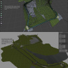
    [​IMG]

    So...Attempt no1

    Using the Open Street Map importer for Blender+google earth overview map image UV mapped on to the terrain and pushing the splines around till everything matched.

    Problem 1:

    I have been using this method for about a month's worth of weekends, creating a mesh from the splines generated for the track from OSM, but these were slightly off when compared to the textured terrain. I have read on here that because Google Maps is mapped to a globe, you get distortions the further from the centre of the image and especially if there are large z co-ord changes i.e. buildings, big pointy hills, etc.

    The bottom hair pin was off, the west to east straight at the top of the track was too high up by a few meters so I moved the splines to compensate.

    Problem 2:

    After fixing all this, creating geometry for the areas the cars can drive on and blocking out the infield ground (cutting in roads, car parks, the field/parking area to the left of the second straight, it was looking good and started to create textures, uv mapping the track and the driveable areas so I can better picture what I had.

    I then started running youtube on one half of the screen whilst having blender in the other and watched track day footage just to see if the general shape of the track seemed ok... so far so good...

    However after seeing some camera shots of the hairpin that is used to cut out the southern part of the track on a BTCC video, the infield section and contours of the track seemed off. BUGGER!!

    It seems the Terrain mesh imported from Open Street Map is not high enough for this task.

    Sooooooo.....

    After reading up on using LIDAR, I have decided to take t he plunge and go down this route.

    I initially used a decimated mesh to act as the terrain mesh but I went too far with it (welding vertices within 2-3metres, but the problem with this is that you lose the subtle details that can act as landmarks for getting the track placed properly or making sure the gravel traps are in the right places.

    So I have re-imported the STL to my track scene and now currently removing all these bloody trees and anything that obscures the track surface such as bridges and gantries. I had to choose a wooded area for my first track! :lol:

    Next up is to finish cleaning up the LIDAR mesh, and start the fun task of figuring out where the track outline is on it and matching my track up...
     
    Tibor Solyom and luchian like this.
  2. LilSKi

    LilSKi Well-Known Member

    Joined:
    Apr 6, 2015
    Messages:
    370
    Likes Received:
    329
    Does the data have intensity data in it? If so you can use that to map out the layout as the track will be black.
     
    ChunkiEgg likes this.
  3. Johnr777

    Johnr777 Moderator

    Joined:
    Jul 26, 2017
    Messages:
    1,050
    Likes Received:
    614
    Through that link in the "lidar" thread, I was able to find LAZ point cloud tiles for that location... so I'm almost sure there's intensity in it.
     
    ChunkiEgg likes this.
  4. ChunkiEgg

    ChunkiEgg New Member

    Joined:
    May 18, 2019
    Messages:
    18
    Likes Received:
    23
    Location:
    Hampshire, UK
    Sounds like I need to read up some more on the LIDAR thread- I followed the guide to create the STL file, which I then imported in to Blender, and using the pit lane as my land mark, aligned the LIDAR generated mesh with the OSM terrain and the low poly meshes.

    The work method I am currently using is to use the shrink wrap modifier on the low poly assets and project to outside surface, affecting the positve and minus Z axis. This is how the OSM importer works with placing landmarks and roads to the terrain and I thought it was a bloody handy way of doing this :)

    I will do some bedtime reading of the LIDAR thread to find out more about the process and see where I can improve the LIDAR data's effectiveness.

    Thanks again for the heads up on this, it's one of the reasons why I had to get my backside in gear and post on here :D
     
  5. ChunkiEgg

    ChunkiEgg New Member

    Joined:
    May 18, 2019
    Messages:
    18
    Likes Received:
    23
    Location:
    Hampshire, UK
    I've had another look through https://assettocorsamods.net/threads/lidar-point-cloud-to-mesh-tutorial.422/ but couldn't see anything about the intensity maps- would it be possible to get a link on how to generate and use the intensity maps please? I am very curious! :)

    I have been pondering over some possible workflows to create the off track areas so they are efficient but detailed via the sculpt brush tool and dynamic topology. Going to do some tests once I have nail down the driveable area and if it works, I'll make a little demonstration.

    Things might be slow in regards to updates as the next few weekends (when I get chance to work on the track) are pretty full on, but will keep an eye out on here when I can :)
     
  6. Johnr777

    Johnr777 Moderator

    Joined:
    Jul 26, 2017
    Messages:
    1,050
    Likes Received:
    614
    Try these circled settings, then proceed to save the mesh as you have been unknown.png
     
    ChunkiEgg and luchian like this.
  7. ChunkiEgg

    ChunkiEgg New Member

    Joined:
    May 18, 2019
    Messages:
    18
    Likes Received:
    23
    Location:
    Hampshire, UK
    Aha! I've re-exported out the LIDAR data with this selected, not really noticed a big difference, but I have saved myself a hell of a lot of time removing the trees, gantries and buildings from the LIDAR mesh in a non-destructive way and all by a happy little accident :D

    I will write up a guide on how I did this next week (I'm waiting for a process at work to finish and off for a break over the weekend but will be back Monday) as this might be of use for other Blender users :)
     
  8. Johnr777

    Johnr777 Moderator

    Joined:
    Jul 26, 2017
    Messages:
    1,050
    Likes Received:
    614
    No luck with getting intensity to show?
     
    ChunkiEgg likes this.
  9. ChunkiEgg

    ChunkiEgg New Member

    Joined:
    May 18, 2019
    Messages:
    18
    Likes Received:
    23
    Location:
    Hampshire, UK
    Update time!

    I went back through the process and realised I had missed a few stages. I found the intensity option and after merging all the cloud sectors in to one so I could visualize the scene better I did the following:

    1. Removed the tree coverage by segmenting the area that had trees, then using the cross section tool to remove large amounts without much effort.

    2. Using the intensity display, I then started segmenting the track from the surrounding areas, and then segmenting the areas that the user can drive on i.e. the grassy areas, gravel traps and so forth. Took a bit of time but it gave me the shapes I needed.

    3. Once all this was done, I exported to Blender 2.80, and whilst still retaining the original LIDAR data I had used originally, and using the new lidar track shape, moved the low poly version around until it matched. The Lidar track did look rough on some of the outer edges but there was enough for me to get the track's edge very close.

    4. I then displayed the low poly driveable areas and discovered there's a ton of work to do to match it all up to the track again which after taking me all my free time to do in the first place, is not a very attractive prospect.

    At this point my heart dropped.. but I have a mad idea which means throwing away all my low poly work apart from the track but could potentially work really well...

    First things first, I have taken the old terrain plane that I imported from Open Street Maps which I had mapped a texture created by doing loads of screen grabs of google maps satellite photo mode and because it was laid out over the original LIDAR mesh, I could use use the Shrink Wrap modifier. I then pushed and pulled the vertices which in turn distorted the texture and using the low poly track, matched up the satellite imagery. The infield and areas beyond the track are probably still distorted but it means I have a reference point I can go to at any point i.e. placement of bump strips, material changes on the ground i.e. final corner features concrete just beyond the track limits before heading in to the gravel trap.

    Now for the fun bit. I have only just started this process, but the plan is to take all the new LIDAR data which is still in segments (inside driveable areas, outside driveable areas, grass islands, gravel traps, pit buildings and bridges) and decimate them down so they're at a low enough density to be useable.

    I will then make them mate up to the low poly track mesh and where the LIDAR point density was higher than surrounding areas as there is a diagonal strip of really dense data running from the N0rth-West to South-East corner, use the sculpting tool's simplify brush to make everything consistent.

    Now... this is where it gets interesting. Beforehand, I had created the track shape, and then extruded from the edge to where the outer edges of the driveable areas were and added additional loops. This meant I could have clean geometry that I could then break up in to grass verge textures for where the grass meets the track, a tiling grass texture that was flat and could be tiled or use grass that had varying length, to indicate someone had cut the grass (you can notice this all around the track from what I've seen on youtube videos).

    The problem now is that because the geometry is going to be more messier, I will either need to cut in to the mesh to give a nice consistent edge loop and UV seams to continue this method, or I need to look at another way of displaying different textures.

    Sorry for the lack of images but as soon as I figure this out I will update with images :)
     
    Tibor Solyom likes this.
  10. ChunkiEgg

    ChunkiEgg New Member

    Joined:
    May 18, 2019
    Messages:
    18
    Likes Received:
    23
    Location:
    Hampshire, UK


    Right, update time... sorry for the rambling but this is becoming my dev diary, which may help any other newbie track builders out there. I have worked as a prop/character/environment artist on handheld and PS2/Wii era consoles.

    Anyhows, I tried my idea out and made some notes and a video doing a run through of where I am currently with the track. I outline some of the things mentioned below but thought that instead of faffing with loads of images, I'd do a proper run through. Sorry for the length, I did try to remove as much empty space as I didn't plan what I was going to say so apologies :D

    For more information, here's the notes of what I've been doing and experiments.

    Original workflow: extract the terrain and road meshes from Open Street Map and use these as the basis for the real-time environment.

    Conclusion: This method is not accurate enough for highly detailed environments. Initially used the track road mesh and subdivided but too many vertices to work with.

    Experiments:

    The aim: Take the raw untreated meshes generated by Cloud Compare, and using the tools in Blender 2.8, optimise them enough to be useable for the realtime application.

    Method 1: Decimate modifier. Benefits: quickly reduce the triangle count of a mesh by a percentage. If a mesh has evenly distributed geometry, this works well. However, in the case of the LIDAR sourced meshes, the density can vary greatly. Example is Oulton Park's LIDAR data, where there are strips of dense geometry and other strips that are half the detail. Using the decimate modifier on a single mesh will keep the proportion of density but reduces the vertex/triangle count evenly across the range.

    Further notes:

    If the point clouds are kept seperate from each other so when the meshes in Cloud Compare are generated and exported to Blender, it will be easy use the decimate tool on each section separately until the density is the same. This would mean a lot of clean up, stitching each segment to the next.

    Method 2: Using the Sculpt tool Simplify. This has some potential. But performance takes a hit using the sculpt tool with such a dense mesh. Also simplify is based on camera location and how far away the camera is from the geometry. Plus it can actually add vertices too.

    To Try next: Take the lower density areas of a mesh, using a low pixel distance setting Simplify tool and combine with the Decimate tool. This would decimate the mesh in a consistent fashion.

    New Methodology:

    Because of the arse about face method I initially used (This is my first large scale environment that is not modular or contained within a small area, and more used to props and characters :D) I ended up using methods that would take a long time to do properly and I want to create a beta version of the track before January 2020. Partially because I know that after April-May time I will be working on my car which is currently off the road (needs coilovers adding, new exhaust, possibly wider arches and widen the track of the car and vinyl wrap it).

    So after reading up some more and watching a lot of youtube videos, I changed my methodology.

    I created the splines for the outer track, pit lane, and all the small alternative routes for the different track configurations, and created a 10m x3m track section mesh, nicely uv mapped and then added an off track area that is about 2m wide each side.

    Using the Array tool, and setting length to the match the curve length of the section I wanted to create the track for, then moved on to adding the Curve modifier and once again, selecting the curve I wanted.

    Something I found that was really useful with the curve editing was that you can define the width/thickness of the mesh that will be placed there. I used this a lot for when the track/pit lane changed width and worked really well.

    I have also blocked out the buildings that are visible from the track apart from the large gate building by the final bend but this is low priority.
     
    luchian, MGMetroDave and Johnr777 like this.
  11. MGMetroDave

    MGMetroDave Active Member

    Joined:
    Apr 7, 2019
    Messages:
    141
    Likes Received:
    159
    Hi @ChunkiEgg . Really nice work! The bezier curve, and subsequently the attached mesh, can be made more smooth by changing the number of subdivisions between control points in the curve properties tab of the curve object. Default I think is 12 and it can go up to 64 if I recall. If that's not enough, e.g if setting to 64 isn't enough to smooth your curve, you can add a control point to your curve between 2 existing ones in edit mode.

    Regarding decimating different areas differently, there are probably many ways to do it. One option I've seen some track modders use is to have a lower poly mesh for the ground of the larger area that covers the entire area. This is then lowered a bit, perhaps 0.1m or maybe more so it technically continues under the track. Then the drivable areas of the track are a separate mesh above it, with walls and objects to stop the player driving off the drivable mesh and to obscure the edge of the drivable mesh, if that makes sense. Not sure if that's exactly what you're after?

    As far as I know there's no bump map support native in AC. For players using Shaders Patch there's now the ability to use parallax displacement maps, but not all players will have CSP. So depending on what shaders you choose to use in kseditor, some have support for these maps: normal, specular, roughness, glossy and diffuse obviously. It depends which shaders you're using though. If you're making or using normal maps from other sources, keep in mind that in AC the red channel is left-to-right with left being white and right black, and green channel is top to bottom with up being white and down black. If you have a normal map that doesn't match that, you can easily invert the respective channel using Photoshop or another editor to make sure you have shading in the right places on your material in game. Just saying this because very often normal maps from sources such as textures.com have the red channel the other way round. Not sure if that makes sense but hope it helps!
     
    ChunkiEgg likes this.
  12. MGMetroDave

    MGMetroDave Active Member

    Joined:
    Apr 7, 2019
    Messages:
    141
    Likes Received:
    159
  13. ChunkiEgg

    ChunkiEgg New Member

    Joined:
    May 18, 2019
    Messages:
    18
    Likes Received:
    23
    Location:
    Hampshire, UK
    Thanks for the heads up about the curves, I will be upping the number of steps and seeing how that works out.
    I have already started adding more points in the curves as I needed to refine the width of the track at various points. Did a lot of work last night coming up with a game plan on how to merge the short cut sections that create new configurations of tracks.

    Another thing I am trying to plan ahead with is changing the track texture so it contains the differing surfaces where repairs have been made that are different colours. The white line will not be part of the main road surface but can be a smaller element within the texture, and then cutting in the geometry for the markings, allowing me to more easily place markings like where the track branches off, where there are dashed lines (where the second chicane is on the western straight before heading up the hill).

    I will keep in mind what you have mentioned about the lower poly outer areas, I am thinking that if I simplify it down enough and remove all non landscape features, it should be enough. I was going to use it for the immediate run off areas but this causes issues with UV seams. The aim is to get this really optimal as the trees could create a headache as there are so many of them on the outside of the track.

    And a big thankyou for the heads up on the shaders and what is supported- I will need to find a normal map generator or possibly see if Blender will output to normal based on the bump... I am even thinking about creating my own grass models and render to texture, so the normal and specular are baked to texture from the geometry and materials... so many possibilities! :D

    And I have bookmarked the link you supplied in your other post, again it is much appreciated! :)

    I may see if I can jump on this later today after work but probably end up being next weekend that I will be jumping on this again.
     
    MGMetroDave likes this.
  14. MGMetroDave

    MGMetroDave Active Member

    Joined:
    Apr 7, 2019
    Messages:
    141
    Likes Received:
    159
    Excellent, yeah it's a steep learning curve I'm finding, but fun! One thing you might find useful is, rather than 'cut in' the geometry for the markings, it's often better to have a separate mesh for the white lines, hovering it a little above the track mesh (I use 0.01m but that's just me) It's not noticable that it's slightly above. That way the track mesh stays clean, and means less triangles to render. Similar goes for adding some track defects, if they're small. In fact, if you take a look at good examples of AC tracks, if you press F7 and fly around, go in close to some white lines and other details and you'll notice they're overlayed a little above the track mesh.

    Keep up the good work, and great choice of circuit! :D
     
    ChunkiEgg likes this.
  15. MGMetroDave

    MGMetroDave Active Member

    Joined:
    Apr 7, 2019
    Messages:
    141
    Likes Received:
    159
    Forgot to say, there are DDS plugins for Photoshop and Gimp.

    I've not used the gimp one, but I use the photoshop one and it's good, and it includes a converter for bump -> nm. Again, just make sure that the finished normal map channels are the correct way round for AC and invert them if necessary.

    Photoshop DDS plugin available here: https://developer.nvidia.com/nvidia-texture-tools-adobe-photoshop (not sure where to get the gimp version sorry)
     
    ChunkiEgg likes this.
  16. ChunkiEgg

    ChunkiEgg New Member

    Joined:
    May 18, 2019
    Messages:
    18
    Likes Received:
    23
    Location:
    Hampshire, UK
    Thanks again Dave, and once again, some gems that will save me time regarding the track markings- hadn't even thought of this and solves a lot of possible issues I am facing i.e creating extra textures for things like chevron road markings for the pit entry, and also where the pit boxes are separated from the pit lane.

    Definitely going to be faffing with this tonight, I'm itching to have a play :D

    I am using Affinity Photo, which allegedly allows the use of Photoshop plugins but pretty sure the Nvidia normal map generator plugin doesn't work with it, boooo! I used to love using it on Photoshop CS2 :D I used to do a lot of cheating with photo based textures by creating the basic volumes in 3DS Max and then using layer effects to generate height maps, convert to normal and overlay on the volumes. Saved a lot of time when deadlines were looming! :)
     
    MGMetroDave likes this.
  1. This site uses cookies to help personalise content, tailor your experience and to keep you logged in if you register.
    By continuing to use this site, you are consenting to our use of cookies.
    Dismiss Notice